Product Description
Foot Mounted Planar Double Enveloping Worm Reduction Gearbox Appilcation For Mixer
As 1 of famous double enveloping worm gear manufacturers,SGR’s double throated worm gear has advantage of High efficiency, low noise, smooth operation , it increase output torque that mean increasing loading capacity , improved gear accuracy, and extended Long life service period . in SGR double enveloping worm gear design ,based on different ratio, it has Multi-tooth meshed, allowed bigger CHINAMFG load . with the increase of number of driven gear teeth , that mean in contact with the worm significantly increases output torque force. except increasing the number of driven gear teeth in contact with the worm, double enveloping worm gear also increase the contact surface on every gear tooth. The actual gear surface of instantaneous contact between the double throated and the driven gear tooth are in-lines. These lines of contact move across the face of the gear tooth as it progresses through its total time of mesh with the worm. The lines of contact in double enveloping worm gear are configured to increase the force and decrease the stress on every gear tooth.
Datasheet on CUW double enveloping worm gear reducer :
| Model | ShaftDia. (mm) | Center Height (CUW) | (CUW) Output shaft Dia. | Power | Ratio | Permitted Torque | Weight |
| (CUW) input Solid(h6) | (mm) | (mm) | (kw) | (Nm) | (KGS) | ||
| 100 | 28 | 190 | 48 | 1.41~11.5 | 10 .25~ 62 | 683-1094 | 42 |
| 125 | 32 | 225 | 55 | 2.42~19.7 | 10 .25 ~ 62 | 1170~2221 | 65 |
| 140 | 38 | 255 | 65 | 3.94~25.9 | 10 .25 ~ 62 | 1555 ~ 3473 | 85 |
| 160 | 42 | 290 | 70 | 4.39~35.7 | 10 .25 ~ 62 | 2143 ~4212 | 120 |
| 180 | 48 | 320 | 80 | 5.83~47.5 | 10 .25 ~ 62 | 2812 ~ 5387 | 170 |
| 200 | 55 | 350 | 90 | 7.52 ~61.2 | 10 .25 ~ 62 | 3624 ~6859 | 220 |
| 225 | 60 | 390 | 100 | 9.9~81.4 | 10 .25 ~ 62 | 4872 ~ 9224 | 290 |
| 250 | 65 | 430 | 110 | 12.9 ~105 | 10 .25~ 62 | 6284~11892 | 380 |
| 280 | 70 | 480 | 120 | 16.9 ~ 138 | 10 .25 ~ 62 | 8347 ~ 15820 | 520 |
| 315 | 75 | 530 | 140 | 22.5 ~183 | 10 .25 ~ 62 | 11068~ 19450 | 700 |
| 355 | 80 | 595 | 150 | 30~245 | 10 .25 ~ 62 | 14818 ~28014 | 1030 |
| 400 | 90 | 660 | 170 | 32.1 ~261 | 10 .25 ~ 62 | 15786~29918 | 1400 |
| 450 | 100 | 740 | 190 | 42.6 ~347 | 10 .25 ~ 62 | 2571~39881 | 1980 |
| 500 | 110 | 815 | 210 | 54.9 ~ 448 | 10 .25 ~ 62 | 27097~51180 | 2700 |
/* March 10, 2571 17:59:20 */!function(){function s(e,r){var a,o={};try{e&&e.split(“,”).forEach(function(e,t){e&&(a=e.match(/(.*?):(.*)$/))&&1
| Application: | Motor, Machinery |
|---|---|
| Hardness: | Hardened Tooth Surface |
| Installation: | Horizontal Type |
| Layout: | Coaxial |
| Gear Shape: | Bevel Gear |
| Step: | Single-Step |
| Samples: |
US$ 2000/Piece
1 Piece(Min.Order) | |
|---|
| Customization: |
Available
| Customized Request |
|---|
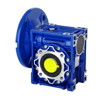
How to Install and Align a Worm Reducer Properly
Proper installation and alignment of a worm reducer are crucial for ensuring optimal performance and longevity. Follow these steps to install and align a worm reducer:
- Preparation: Gather all the necessary tools, equipment, and safety gear before starting the installation process.
- Positioning: Place the worm reducer in the desired location, ensuring that it is securely mounted to a stable surface. Use appropriate fasteners and mounting brackets as needed.
- Shaft Alignment: Check the alignment of the input and output shafts. Use precision measurement tools to ensure that the shafts are parallel and in line with each other.
- Base Plate Alignment: Align the base plate of the reducer with the foundation or mounting surface. Ensure that the base plate is level and properly aligned before securing it in place.
- Bolt Tightening: Gradually and evenly tighten the mounting bolts to the manufacturer’s specifications. This helps ensure proper contact between the reducer and the mounting surface.
- Check for Clearance: Verify that there is enough clearance for any rotating components or parts that may move during operation. Avoid any interference that could cause damage or performance issues.
- Lubrication: Apply the recommended lubricant to the worm reducer according to the manufacturer’s guidelines. Proper lubrication is essential for smooth operation and reducing friction.
- Alignment Testing: After installation, run the worm reducer briefly without a load to check for any unusual noises, vibrations, or misalignment issues.
- Load Testing: Gradually introduce the intended load to the worm reducer and monitor its performance. Ensure that the reducer operates smoothly and efficiently under the load conditions.
It’s important to refer to the manufacturer’s installation guidelines and specifications for your specific worm reducer model. Proper installation and alignment will contribute to the gearbox’s reliability, efficiency, and overall functionality.
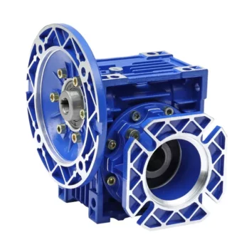
How to Calculate the Input and Output Speeds of a Worm Gearbox?
Calculating the input and output speeds of a worm gearbox involves understanding the gear ratio and the principles of gear reduction. Here’s how you can calculate these speeds:
- Input Speed: The input speed (N1) is the speed of the driving gear, which is the worm gear in this case. It is usually provided by the manufacturer or can be measured directly.
- Output Speed: The output speed (N2) is the speed of the driven gear, which is the worm wheel. To calculate the output speed, use the formula:
N2 = N1 / (Z1 * i)
Where:
N2 = Output speed (rpm)
N1 = Input speed (rpm)
Z1 = Number of teeth on the worm gear
i = Gear ratio (ratio of the number of teeth on the worm gear to the number of threads on the worm)
It’s important to note that worm gearboxes are designed for gear reduction, which means that the output speed is lower than the input speed. Additionally, the efficiency of the gearbox, friction, and other factors can affect the actual output speed. Calculating the input and output speeds is crucial for understanding the performance and capabilities of the worm gearbox in a specific application.
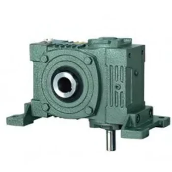
Advantages of Using a Worm Reducer in Mechanical Systems
Worm reducers offer several advantages that make them suitable for various mechanical systems:
- High Gear Reduction Ratio: Worm gearboxes provide significant speed reduction, making them ideal for applications that require a high gear reduction ratio without the need for multiple gears.
- Compact Design: Worm reducers have a compact and space-saving design, allowing them to be used in applications with limited space.
- Self-Locking: Worm gearboxes exhibit self-locking properties, which means that the worm screw can prevent the worm wheel from reversing its motion. This is beneficial for applications where the gearbox needs to hold a load in place without external braking mechanisms.
- Smooth and Quiet Operation: Worm gearboxes operate with a sliding motion between the teeth, resulting in smoother and quieter operation compared to some other types of gearboxes.
- High Torque Transmission: Worm gearboxes can transmit high torque levels, making them suitable for applications that require powerful torque output.
- Heat Dissipation: The sliding action between the worm screw and the worm wheel contributes to heat dissipation, which can be advantageous in applications that generate heat during operation.
- Stable Performance: Worm reducers offer stable and reliable performance, making them suitable for continuous operation in various industrial and mechanical systems.
Despite these advantages, it’s important to note that worm gearboxes also have limitations, such as lower efficiency compared to other gear types due to the sliding motion and potential for higher heat generation. Therefore, selecting the appropriate type of gearbox depends on the specific requirements and constraints of the application.


editor by CX 2024-02-25
China supplier Nrv090 Worm Gearbox Worm Reduction Gearbox Double Output Worm Gearboxes sequential gearbox
Product Description
Product Deascription
Specification
| Brand | CSZBTR |
| Moddel No | NRV090 |
Other Models
| Old Model | New Model | Ratio | Center Distance | Power |
| RV571 | 7.5~100 | 25mm | 0.06KW~0.12KW | |
| RV030 | RW030 | 7.5~100 | 30mm | 0.06KW~0.25KW |
| RV040 | RW040 | 7.5~100 | 40mm | 0.09KW~0.55KW |
| RV050 | RW050 | 7.5~100 | 50mm | 0.12KW~1.5KW |
| RV063 | RW063 | 7.5~100 | 63mm | 0.18KW~2.2KW |
| RV075 | RW075 | 7.5~100 | 75mm | 0.25KW~4.0KW |
| RV090 | RW090 | 7.5~100 | 90mm | 0.37KW~4.0KW |
| RV110 | RW110 | 7.5~100 | 110mm | 0.55KW~7.5KW |
| RV130 | RW130 | 7.5~100 | 130mm | 0.75KW~7.5KW |
| RV150 | RW150 | 7.5~100 | 150mm | 2.2KW~15KW |
Application
Company Profile
HangZhou Terry Machinery Co.Ltd is a leading supplier of bearings, linear motion system
for CNC,ball transfer unit and transmission component. The growing industrial and favorable
policy of HangZhoubenefit the development of Terry Machinery.Our products are utilized in
industrial, motorcycle, vehicleand Automation applications. Now we are exporting to 46
countries includingUSA, GBR, Germany, Spain,Poland, Turkey ect. The goal of Terry Machinery
to provide out customers with widest range of productsatcompetitive prices, backed with the
best Service.
Packing & Deliverey
FAQ
| Application: | Motor, Electric Cars, Motorcycle, Machinery, Marine, Agricultural Machinery, Car |
|---|---|
| Hardness: | Hardened Tooth Surface |
| Installation: | Vertical Type |
| Layout: | Coaxial |
| Gear Shape: | Conical – Cylindrical Gear |
| Step: | Single-Step |
| Samples: |
US$ 145/Piece
1 Piece(Min.Order) Worm Gearbox Applications in Robotics and AutomationWorm gearboxes play a crucial role in various robotics and automation applications due to their unique characteristics and benefits. Here are some common applications where worm gearboxes are used:
Worm gearboxes are preferred in these applications due to their compact size, high torque output, self-locking feature, and ability to provide a right-angle drive. However, selecting the right gearbox requires considering factors such as load, speed, efficiency, and environmental conditions. | |
|---|
Types of Worm Gear Configurations and Their Uses
Worm gear configurations vary based on the arrangement of the worm and the gear it engages with. Here are common types and their applications:
- Single Enveloping Worm Gear: This configuration offers high torque transmission and efficiency. It’s used in heavy-duty applicati
Can a Worm Gearbox Be Used in Heavy-Duty Machinery?
Yes, a worm gearbox can be used in heavy-duty machinery and is often chosen for such applications due to its inherent characteristics and advantages:
- High Torque Transmission: Worm gearboxes are known for their ability to transmit high torque loads, making them suitable for heavy-duty machinery that requires significant power transmission.
- Load Distribution: The design of worm gears provides robust load distribution and excellent contact between the worm and worm wheel teeth. This enhances their load-carrying capacity, making them capable of handling heavy loads without premature wear or failure.
- Compact Design: Worm gearboxes are compact and offer high reduction ratios in a single stage. This allows for the reduction of high input speeds to lower output speeds, often required in heavy-duty machinery.
- Overload Protection: Worm gears have a natural self-locking feature, which means the gear cannot be easily back-driven by external forces. This feature provides inherent overload protection, preventing damage to the gearbox and machinery in cases of sudden load spikes.
- Smooth Operation: Worm gearboxes offer smooth and steady operation, which is crucial for heavy-duty machinery where precision and controlled movement are essential.
However, when considering the use of a worm gearbox in heavy-duty applications, it’s important to ensure proper engineering and sizing. The design should account for factors such as load, speed, duty cycle, lubrication, and temperature to ensure optimal performance and longevity.
Overall, worm gearboxes are well-suited for heavy-duty machinery across various industries, including mining, construction, manufacturing, and more.
ons like mining equipment and industrial machinery.
- Double Enveloping Worm Gear: With increased contact area, this type provides higher load capacity and improved efficiency. It’s used in aerospace applications, robotics, and precision machinery.
- Non-Throated Worm Gear: This type has a cylindrical worm without a throat. It’s suitable for applications requiring precise motion control, such as CNC machines and robotics.
- Throated Worm Gear: Featuring a throat in the worm, this configuration offers smooth engagement and higher load capacity. It’s used in conveyors, elevators, and automotive applications.
- Non-Modular Worm Gear: In this design, the worm and gear are a matched set, resulting in better meshing and efficiency. It’s utilized in various industries where customization is essential.
- Modular Worm Gear: This type allows interchangeability of worm and gear components, providing flexibility in design and maintenance. It’s commonly used in conveyors, mixers, and material handling systems.
Selecting the appropriate worm gear configuration depends on factors such as load capacity, efficiency, precision, and application requirements. Consulting gearbox experts can help determine the best configuration for your specific needs.


editor by CX 2023-08-16
China Involute Spur Gear Machine Nmrv Worm Speed Reducer Worm Reduction Gearbox double output worm gearbox
Merchandise Description
Feature
one.Housing:Aluminium Alloy
2. lower sound(<50DB)
three.Model:NMRV 25-one hundred fifty,Ratio:10 to 100
4.Successful and safe operating
5.ISO9001,Factory price,OEM
|
Kind: |
reduction gearbox |
|
Model: |
NMRV25-a hundred and fifty |
|
Ratio: |
1:10,fifteen,20,twenty five,thirty,40,fifty,60,eighty,100 |
|
Shade: |
Blue/Silver Or On Buyer Ask for |
|
Substance: |
Housing: Die-Forged Aluminum Alloy |
|
Worm Equipment-Copper-10-3# |
|
|
Worm-20CrMn Ti with carburizing and quenching, area harness is 56-62HRC |
|
|
Shaft-chromium metal-45# |
|
|
Packing: |
Carton and Wooden Scenario |
|
Bearing: |
C&U Bearing |
|
Seal: |
NAK OTHER |
|
Guarantee: |
1 12 months |
|
Input Energy: |
.06KW,.09KW |
|
Usages: |
Industrial Device: Foods Stuff, Ceramics,CHEMICAL,Packing,Dyeing, |
|
IEC Flange: |
56B14, 63B14, 63B5, 63B5, 71B14,80B14 AND SO ON |
|
Lubricant: |
Synthetic&Mineral |
|
US $50 / Piece | |
1 Piece (Min. Order) |
###
| Application: | Motor, Electric Cars, Motorcycle, Machinery, Marine, Toy, Agricultural Machinery, Car |
|---|---|
| Function: | Distribution Power, Clutch, Change Drive Torque, Change Drive Direction, Speed Changing, Speed Reduction, Speed Increase |
| Layout: | Three-Ring |
| Hardness: | Soft Tooth Surface |
| Installation: | Torque Arm Type |
| Step: | Stepless |
###
| Samples: |
US$ 50/Piece
1 Piece(Min.Order) |
|---|
###
|
Type:
|
reduction gearbox
|
|
Model:
|
NMRV25-150
|
|
Ratio:
|
1:10,15,20,25,30,40,50,60,80,100
|
|
Color:
|
Blue/Silver Or On Customer Request
|
|
Material:
|
Housing: Die-Cast Aluminum Alloy
|
|
Worm Gear-Copper-10-3#
|
|
|
Worm-20CrMn Ti with carburizing and quenching, surface harness is 56-62HRC
|
|
|
Shaft-chromium steel-45#
|
|
|
Packing:
|
Carton and Wooden Case
|
|
Bearing:
|
C&U Bearing
|
|
Seal:
|
NAK OTHER
|
|
Warranty:
|
1 Year
|
|
Input Power:
|
0.06KW,0.09KW
|
|
Usages:
|
Industrial Machine: Food Stuff, Ceramics,CHEMICAL,Packing,Dyeing,
Woodworking,Glass. |
|
IEC Flange:
|
56B14, 63B14, 63B5, 63B5, 71B14,80B14 AND SO ON
|
|
Lubricant:
|
Synthetic&Mineral
|
|
US $50 / Piece | |
1 Piece (Min. Order) |
###
| Application: | Motor, Electric Cars, Motorcycle, Machinery, Marine, Toy, Agricultural Machinery, Car |
|---|---|
| Function: | Distribution Power, Clutch, Change Drive Torque, Change Drive Direction, Speed Changing, Speed Reduction, Speed Increase |
| Layout: | Three-Ring |
| Hardness: | Soft Tooth Surface |
| Installation: | Torque Arm Type |
| Step: | Stepless |
###
| Samples: |
US$ 50/Piece
1 Piece(Min.Order) |
|---|
###
|
Type:
|
reduction gearbox
|
|
Model:
|
NMRV25-150
|
|
Ratio:
|
1:10,15,20,25,30,40,50,60,80,100
|
|
Color:
|
Blue/Silver Or On Customer Request
|
|
Material:
|
Housing: Die-Cast Aluminum Alloy
|
|
Worm Gear-Copper-10-3#
|
|
|
Worm-20CrMn Ti with carburizing and quenching, surface harness is 56-62HRC
|
|
|
Shaft-chromium steel-45#
|
|
|
Packing:
|
Carton and Wooden Case
|
|
Bearing:
|
C&U Bearing
|
|
Seal:
|
NAK OTHER
|
|
Warranty:
|
1 Year
|
|
Input Power:
|
0.06KW,0.09KW
|
|
Usages:
|
Industrial Machine: Food Stuff, Ceramics,CHEMICAL,Packing,Dyeing,
Woodworking,Glass. |
|
IEC Flange:
|
56B14, 63B14, 63B5, 63B5, 71B14,80B14 AND SO ON
|
|
Lubricant:
|
Synthetic&Mineral
|
What is a worm gear reducer?
A worm gear reducer is a mechanical device that uses a worm gear and a worm to reduce the speed of a rotating shaft. The gear reducer can increase the output torque of the engine according to the gear ratio. This type of gear reducer is characterized by its flexibility and compact size. It also increases the strength and efficiency of the drive.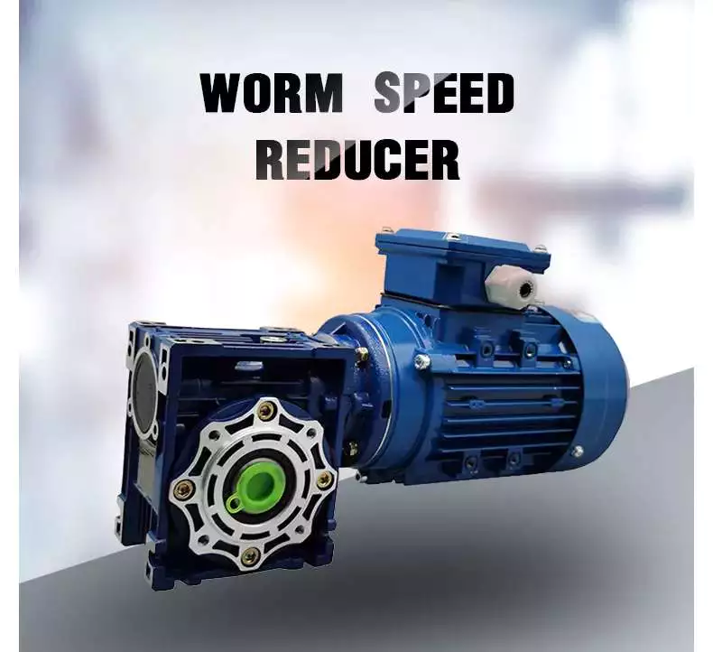
Hollow shaft worm gear reducer
The hollow shaft worm gear reducer is an additional output shaft connecting various motors and other gearboxes. They can be installed horizontally or vertically. Depending on size and scale, they can be used with gearboxes from 4GN to 5GX.
Worm gear reducers are usually used in combination with helical gear reducers. The latter is mounted on the input side of the worm gear reducer and is a great way to reduce the speed of high output motors. The gear reducer has high efficiency, low speed operation, low noise, low vibration and low energy consumption.
Worm gear reducers are made of hard steel or non-ferrous metals, increasing their efficiency. However, gears are not indestructible, and failure to keep running can cause the gear oil to rust or emulsify. This is due to moisture condensation that occurs during the operation and shutdown of the reducer. The assembly process and quality of the bearing are important factors to prevent condensation.
Hollow shaft worm gear reducers can be used in a variety of applications. They are commonly used in machine tools, variable speed drives and automotive applications. However, they are not suitable for continuous operation. If you plan to use a hollow shaft worm gear reducer, be sure to choose the correct one according to your requirements.
Double throat worm gear
Worm gear reducers use a worm gear as the input gear. An electric motor or sprocket drives the worm, which is supported by anti-friction roller bearings. Worm gears are prone to wear due to the high friction in the gear teeth. This leads to corrosion of the confinement surfaces of the gears.
The pitch diameter and working depth of the worm gear are important. The pitch circle diameter is the diameter of the imaginary circle in which the worm and the gear mesh. Working depth is the maximum amount of worm thread that extends into the backlash. Throat diameter is the diameter of the circle at the lowest point of the worm gear face.
When the friction angle between the worm and the gear exceeds the lead angle of the worm, the worm gear is self-locking. This feature is useful for lifting equipment, but may be detrimental to systems that require reverse sensitivity. In these systems, the self-locking ability of the gears is a key limitation.
The double throat worm gear provides the tightest connection between the worm and the gear. The worm gear must be installed correctly to ensure maximum efficiency. One way to install the worm gear assembly is through a keyway. The keyway prevents the shaft from rotating, which is critical for transmitting torque. Then attach the gear to the hub using the set screw.
The axial and circumferential pitch of the worm gear should match the pitch diameter of the larger gear. Single-throat worm gears are single-threaded, and double-throat worm gears are double-throat. A single thread design advances one tooth, while a double thread design advances two teeth. The number of threads should match the number of mating gears.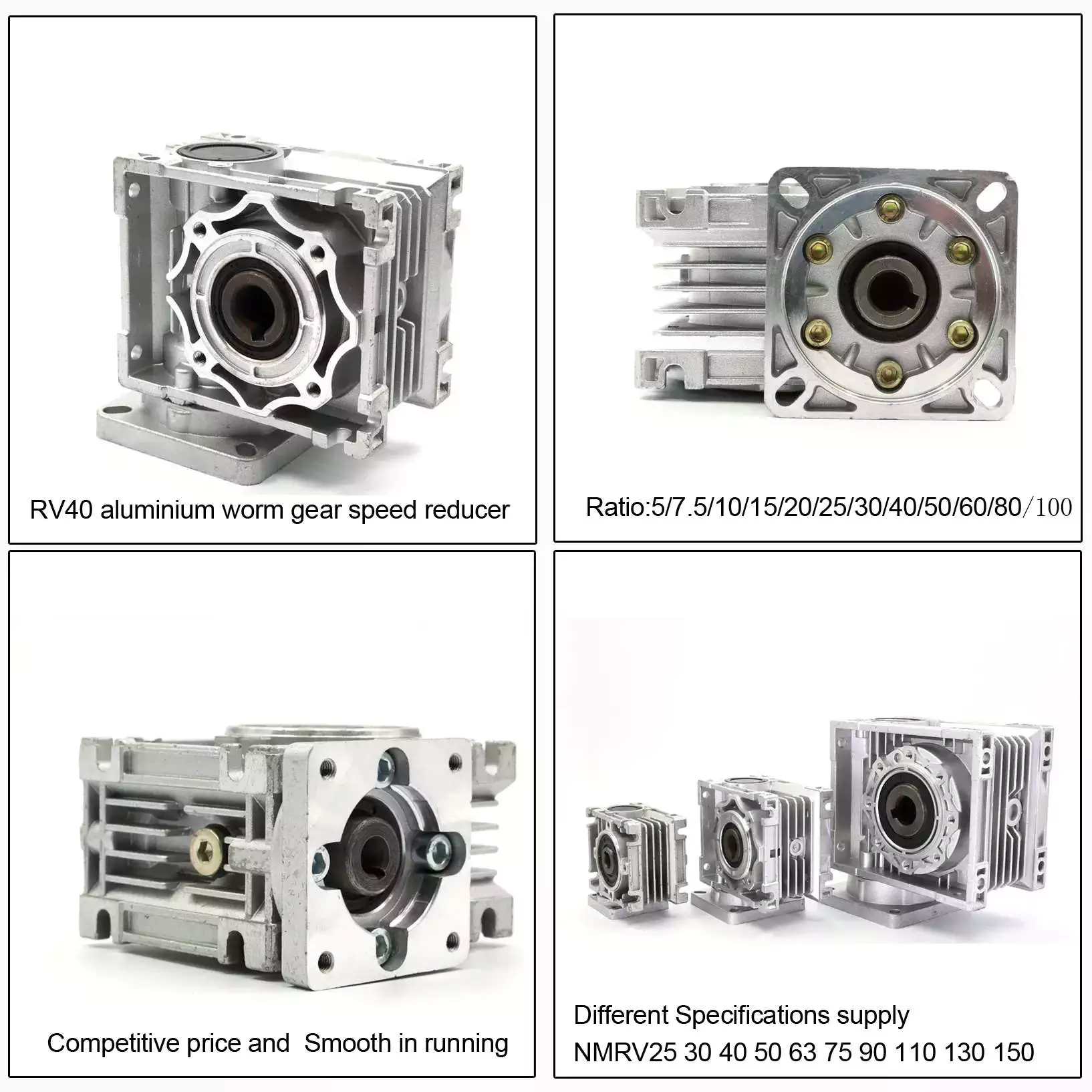
Self-locking function
One of the most prominent features of a worm reducer is its self-locking function, which prevents the input and output shafts from being interchanged. The self-locking function is ideal for industrial applications where large gear reduction ratios are required without enlarging the gear box.
The self-locking function of a worm reducer can be achieved by choosing the right type of worm gear. However, it should be noted that this feature is not available in all types of worm gear reducers. Worm gears are self-locking only when a specific speed ratio is reached. When the speed ratio is too small, the self-locking function will not work effectively.
Self-locking status of a worm reducer is determined by the lead, pressure, and coefficient of friction. In the early twentieth century, cars had a tendency to pull the steering toward the side with a flat tire. A worm drive reduced this tendency by reducing frictional forces and transmitting steering force to the wheel, which aids in steering and reduces wear and tear.
A self-locking worm reducer is a simple-machine with low mechanical efficiency. It is self-locking when the work at one end is greater than the work at the other. If the mechanical efficiency of a worm reducer is less than 50%, the friction will result in losses. In addition, the self-locking function is not applicable when the drive is reversed. This characteristic makes self-locking worm gears ideal for hoisting and lowering applications.
Another feature of a worm reducer is its ability to reduce axially. Worm gears can be double-lead or single-lead, and it is possible to adjust their backlash to compensate for tooth wear.
Heat generated by worm gears
Worm gears generate considerable amounts of heat. It is essential to reduce this heat to improve the performance of the gears. This heat can be mitigated by designing the worms with smoother surfaces. In general, the speed at which worm gears mesh should be in the range of 20 to 24 rms.
There are many approaches for calculating worm gear efficiency. However, no other approach uses an automatic approach to building the thermal network. The other methods either abstractly investigate the gearbox as an isothermal system or build the TNM statically. This paper describes a new method for automatically calculating heat balance and efficiency for worm gears.
Heat generated by worm gears is a significant source of power loss. Worm gears are typically characterized by high sliding speeds in their tooth contacts, which causes high frictional heat and increased thermal stresses. As a result, accurate calculations are necessary to ensure optimal operation. In order to determine the efficiency of a gearbox system, manufacturers often use the simulation program WTplus to calculate heat loss and efficiency. The heat balance calculation is achieved by adding the no-load and load-dependent power losses of the gearbox.
Worm gears require a special type of lubricant. A synthetic oil that is non-magnetic and has a low friction coefficient is used. However, the oil is only one of the options for lubricating worm gears. In order to extend the life of worm gears, you should also consider adding a natural additive to the lubricant.
Worm gears can have a very high reduction ratio. They can achieve massive reductions with little effort, compared to conventional gearsets which require multiple reductions. Worm gears also have fewer moving parts and places for failure than conventional gears. One disadvantage of worm gears is that they are not reversible, which limits their efficiency.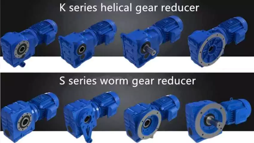
Size of worm gear reducer
Worm gear reducers can be used to decrease the speed of a rotating shaft. They are usually designed with two shafts at right angles. The worm wheel acts as both the pinion and rack. The central cross section forms the boundary between the advancing and receding sides of the worm gear.
The output gear of a worm gear reducer has a small diameter compared to the input gear. This allows for low-speed operation while producing a high-torque output. This makes worm gear reducers great for space-saving applications. They also have low initial costs.
Worm gear reducers are one of the most popular types of speed reducers. They can be small and powerful and are often used in power transmission systems. These units can be used in elevators, conveyor belts, security gates, and medical equipment. Worm gearing is often found in small and large sized machines.
Worm gears can also be adjusted. A dual-lead worm gear has a different lead on the left and right tooth surfaces. This allows for axial movement of the worm and can also be adjusted to reduce backlash. A backlash adjustment may be necessary as the worm wears down. In some cases, this backlash can be adjusted by adjusting the center distance between the worm gear.
The size of worm gear reducer depends on its function. For example, if the worm gear is used to reduce the speed of an automobile, it should be a model that can be installed in a small car.


editor by czh 2022-11-27