Product Description
HangZhou CHINAMFG Machinery Manufacture Co., Ltd
Product Description
Agri Gear Box
Production Workshop
Product Parameters
Packaging & Shipping
Packing:
Normal packing or According to your requirement.
Safe, complete and fast delivery of goods to customers.
Shipping: By sea
Payment Terms: T/T
Company Profile
| Business type | Manufacture |
| Location | Shiliwang Industrial Zone of HangZhou, ZheJiang ,China |
| Year Established | 2003 |
| Occupied area | 50 Acres |
| Company certification | CE, ISO9001,SGS |
| Main product | disc harrow, disc plough, trailer, boom sprayer , rotary tillers, potato planter ,plowing blade, plough blade, soil-loosening shovel and so on. With good quality, excellent performance, our products annually export to countries around the world, and we have gained the majority of customers trust. |
After Sales Service
After Service: 12 months guarantee of the main parts, we will send the guarantee parts together with the machine in your next order or we can send them by air express if you need it urgently.
FAQ
1.Q: Full price list for these products
A: If you need the price list for these products, please notify the product model so that I can quote you accordingly. Please understand we have a very wide product range, we don’t usually offer full products price list.
2. Q: Business terms
A: Shipment time: 25-40days after your payment
Shipment: By sea
Loading port: HangZhou port, China
Destination port: …To be advised
Payment: T/T
Warranty: 1 year
3.Q:How can I order from you?
A: Please send us your enquiry list; we will reply you within 2 working days.
4.Q:If the finger I look for are not in your catalogue, what should I do?
A: We can develop it according to your drawing or sample.
5. Q: Why choose CHINAMFG for cooperation?
A: Comparing with our competitors, we have much more advantages as follows:
– More than 30years in manufacturing farming machine
– More Professional Sales staffs to guarantee the better service
– More agri machines for your choice
– More New products into your range to avoid price competition
– Larger quantity production and shipment
– Better quality to guarantee better Credit.
– Faster delivery time: Only7days
– More stick quality checking before shipment.
– More reasonable after-sales service terms.
– More famous brand: Hongri” brand and “CE”ceitification.
– Lower repair rate and bad review rate
– We have American Branch to show our main products. We can give customers best service.
Please feel free to contact me if you have any questions.
Thanks. Have a nice day!
Contact me
/* January 22, 2571 19:08:37 */!function(){function s(e,r){var a,o={};try{e&&e.split(“,”).forEach(function(e,t){e&&(a=e.match(/(.*?):(.*)$/))&&1
| Application: | Motor, Machinery, Agricultural Machinery |
|---|---|
| Function: | Distribution Power, Clutch, Change Drive Torque |
| Hardness: | Soft Tooth Surface |
| Installation: | Horizontal Type |
| Step: | Double-Step |
| Type: | Worm Gear Box |
| Samples: |
US$ 0/Piece
1 Piece(Min.Order) | |
|---|
| Customization: |
Available
| Customized Request |
|---|
Common Problems and Troubleshooting for Worm Gearboxes
Worm gearboxes, like any mechanical component, can experience various issues over time. Here are some common problems that may arise and possible troubleshooting steps:
- Overheating: Overheating can occur due to factors such as inadequate lubrication, excessive loads, or high operating temperatures. Check lubrication levels, ensure proper ventilation, and reduce loads if necessary.
- Noise and Vibration: Excessive noise and vibration may result from misalignment, worn gears, or improper meshing. Check for misalignment, inspect gear teeth for wear, and ensure proper gear meshing.
- Leakage: Oil leakage can be caused by damaged seals or gaskets. Inspect seals and gaskets, and replace them if necessary.
- Reduced Efficiency: Efficiency loss can occur due to friction, wear, or misalignment. Regularly monitor gearbox performance, ensure proper lubrication, and address any wear or misalignment issues.
- Backlash: Excessive backlash can affect precision and accuracy. Adjust gear meshing and reduce backlash to improve performance.
- Seizure or Binding: Seizure or binding can result from inadequate lubrication, debris, or misalignment. Clean the gearbox, ensure proper lubrication, and address misalignment issues.
- Worn Gears: Worn gear teeth can lead to poor performance. Regularly inspect gears for signs of wear, and replace worn gears as needed.
- Seal Wear: Seals can wear over time, leading to leakage and contamination. Inspect seals regularly and replace them if necessary.
If you encounter any of these problems, it’s important to address them promptly to prevent further damage and maintain the performance of your worm gearbox. Regular maintenance, proper lubrication, and addressing issues early can help extend the lifespan and reliability of the gearbox.

How to Calculate the Input and Output Speeds of a Worm Gearbox?
Calculating the input and output speeds of a worm gearbox involves understanding the gear ratio and the principles of gear reduction. Here’s how you can calculate these speeds:
- Input Speed: The input speed (N1) is the speed of the driving gear, which is the worm gear in this case. It is usually provided by the manufacturer or can be measured directly.
- Output Speed: The output speed (N2) is the speed of the driven gear, which is the worm wheel. To calculate the output speed, use the formula:
N2 = N1 / (Z1 * i)
Where:
N2 = Output speed (rpm)
N1 = Input speed (rpm)
Z1 = Number of teeth on the worm gear
i = Gear ratio (ratio of the number of teeth on the worm gear to the number of threads on the worm)
It’s important to note that worm gearboxes are designed for gear reduction, which means that the output speed is lower than the input speed. Additionally, the efficiency of the gearbox, friction, and other factors can affect the actual output speed. Calculating the input and output speeds is crucial for understanding the performance and capabilities of the worm gearbox in a specific application.

What is a Worm Gearbox and How Does It Work?
A worm gearbox, also known as a worm gear reducer, is a mechanical device used to transmit rotational motion and torque between non-parallel shafts. It consists of a worm screw and a worm wheel, both of which have helical teeth. The worm screw resembles a threaded cylinder, while the worm wheel is a gear with teeth that mesh with the worm screw.
The working principle of a worm gearbox involves the interaction between the worm screw and the worm wheel. When the worm screw is rotated, its helical teeth engage with the teeth of the worm wheel. As the worm screw rotates, it translates the rotational motion into a perpendicular motion, causing the worm wheel to rotate. This perpendicular motion allows the worm gearbox to achieve a high gear reduction ratio, making it suitable for applications that require significant speed reduction.
One of the key features of a worm gearbox is its ability to provide a high gear reduction ratio in a compact design. However, due to the sliding nature of the meshing teeth, worm gearboxes may exhibit higher friction and lower efficiency compared to other types of gearboxes. Therefore, they are often used in applications where efficiency is not the primary concern but where high torque and speed reduction are essential, such as conveyor systems, elevators, automotive steering systems, and certain industrial machinery.


editor by CX 2024-03-27
China high quality Nmrv040-160 Series Right Angle Gearbox gearbox engine
Product Description
Characteristics
Excellent ecological design adds luster to your brand image.
Various Product input,output and mounting design to meet your diverse needs.
The FEA design of the casting housing,which improves the running stability by 30% and effectively reduces the noise of the whole machine.
High precision worm hob is used to process worm gear,which optimizes contact area,ensures lower noise and longer lifespan.
Excellent material and heat treatment process improve products reliability and lifespan.
High reliability and long design life can effectively reduce your use and maintenance costs.
Unique modular design,international production ,faster production and delivery.
Product type
Mounting mode:foot mounted, flange mounted, torque arm mounted.
Output shaft: CHINAMFG shaft, hollow shaft
RFQ
Q:Are you trading company or manufacturer?
A: We are manufacturer with over 20 years’ experience.
Q: How long is your delivery time?
A: Generally it is within 10 days if the goods are in stock, for goods produced as per order, it is within 35 days after confirmation of order.
Q: How long should I wait for the feedback after I send the enquiry?
A: Normally within 12 hours.
Q: What information should I give you to confirm the product?
A: Model/Size, Transmission Ratio, Speed, Shaft directions & Order quantity etc.
Q: Hong long is your product warranty?
A: We offer 12 months warranty from departure date of the goods.
Q: What is your payment terms? T/T 100% in advance for amount less than USD10000.-, 30% T/T in advance , balance before shipment for amount above USD10000.
If you have any other questions, please feel free to contact us below:
HOW TO CONTACT US?
Send your Inquiry Details in the Below, click “Send” Now!
Company Introduction
Get the right gearbox for your equipment.
CHINAMFG knows gearbox. As the leading industry gearbox manufacturer, PSS offers the best power transmission solutions to perfectly meet your specific industry application. On gearbox, CHINAMFG has a lot more to share.
We always satisfy all industries with our gearbox
CHINAMFG strives for 100% satisfaction from customers of all industries. We welcome challenges to offer tailored design or special solution to satisfy customers’ Special needs on applications. We like to make impossibility become possibility.
Key features
Turbine gearboxes and planetary gearboxes are our advantages. Most companies can only manufacture Helical Bevel gearboxes, and we have a strong design team that has now designed turbine gearboxes up to 70, 000 rpm.
Diversity
CHINAMFG offers a vast diversity of gear reducer, geared motor and gearbox. No doubt you are able to find what you need with PTT.
Reliability
CHINAMFG is a trustworthy manufacturer you can rely on, no matter in terms of quality, delivery, pricing, service, etc. It becomes our name tag during our history of servicing our customers.
Capability
CHINAMFG is able to manufacture 200, 000 sets of gear reducers yearly and keeps investing on development of new series product.
We have a large list of our satisfied clients
Among the large list of our satisfied clients, there are many trend-setting top brands in various industries.
Mian products
Helical Gear Units
Bevel-Helical Gear Units
ZYJ Series Gear Units
DY Series Gear Units
P Planetary Gear Units
MLX Series Mill Gear Units
High Speed Gear Units
Non-stand Gear Units
/* January 22, 2571 19:08:37 */!function(){function s(e,r){var a,o={};try{e&&e.split(“,”).forEach(function(e,t){e&&(a=e.match(/(.*?):(.*)$/))&&1
| Application: | Motor, Machinery |
|---|---|
| Function: | Change Drive Torque, Change Drive Direction, Speed Changing, Speed Reduction |
| Layout: | Right Angle |
| Customization: |
Available
| Customized Request |
|---|
.shipping-cost-tm .tm-status-off{background: none;padding:0;color: #1470cc}
|
Shipping Cost:
Estimated freight per unit. |
about shipping cost and estimated delivery time. |
|---|
| Payment Method: |
|
|---|---|
|
Initial Payment Full Payment |
| Currency: | US$ |
|---|
| Return&refunds: | You can apply for a refund up to 30 days after receipt of the products. |
|---|

How to Install and Align a Worm Reducer Properly
Proper installation and alignment of a worm reducer are crucial for ensuring optimal performance and longevity. Follow these steps to install and align a worm reducer:
- Preparation: Gather all the necessary tools, equipment, and safety gear before starting the installation process.
- Positioning: Place the worm reducer in the desired location, ensuring that it is securely mounted to a stable surface. Use appropriate fasteners and mounting brackets as needed.
- Shaft Alignment: Check the alignment of the input and output shafts. Use precision measurement tools to ensure that the shafts are parallel and in line with each other.
- Base Plate Alignment: Align the base plate of the reducer with the foundation or mounting surface. Ensure that the base plate is level and properly aligned before securing it in place.
- Bolt Tightening: Gradually and evenly tighten the mounting bolts to the manufacturer’s specifications. This helps ensure proper contact between the reducer and the mounting surface.
- Check for Clearance: Verify that there is enough clearance for any rotating components or parts that may move during operation. Avoid any interference that could cause damage or performance issues.
- Lubrication: Apply the recommended lubricant to the worm reducer according to the manufacturer’s guidelines. Proper lubrication is essential for smooth operation and reducing friction.
- Alignment Testing: After installation, run the worm reducer briefly without a load to check for any unusual noises, vibrations, or misalignment issues.
- Load Testing: Gradually introduce the intended load to the worm reducer and monitor its performance. Ensure that the reducer operates smoothly and efficiently under the load conditions.
It’s important to refer to the manufacturer’s installation guidelines and specifications for your specific worm reducer model. Proper installation and alignment will contribute to the gearbox’s reliability, efficiency, and overall functionality.
How to Calculate the Input and Output Speeds of a Worm Gearbox?
Calculating the input and output speeds of a worm gearbox involves understanding the gear ratio and the principles of gear reduction. Here’s how you can calculate these speeds:
- Input Speed: The input speed (N1) is the speed of the driving gear, which is the worm gear in this case. It is usually provided by the manufacturer or can be measured directly.
- Output Speed: The output speed (N2) is the speed of the driven gear, which is the worm wheel. To calculate the output speed, use the formula:
N2 = N1 / (Z1 * i)
Where:
N2 = Output speed (rpm)
N1 = Input speed (rpm)
Z1 = Number of teeth on the worm gear
i = Gear ratio (ratio of the number of teeth on the worm gear to the number of threads on the worm)
It’s important to note that worm gearboxes are designed for gear reduction, which means that the output speed is lower than the input speed. Additionally, the efficiency of the gearbox, friction, and other factors can affect the actual output speed. Calculating the input and output speeds is crucial for understanding the performance and capabilities of the worm gearbox in a specific application.
What is a Worm Gearbox and How Does It Work?
A worm gearbox, also known as a worm gear reducer, is a mechanical device used to transmit rotational motion and torque between non-parallel shafts. It consists of a worm screw and a worm wheel, both of which have helical teeth. The worm screw resembles a threaded cylinder, while the worm wheel is a gear with teeth that mesh with the worm screw.
The working principle of a worm gearbox involves the interaction between the worm screw and the worm wheel. When the worm screw is rotated, its helical teeth engage with the teeth of the worm wheel. As the worm screw rotates, it translates the rotational motion into a perpendicular motion, causing the worm wheel to rotate. This perpendicular motion allows the worm gearbox to achieve a high gear reduction ratio, making it suitable for applications that require significant speed reduction.
One of the key features of a worm gearbox is its ability to provide a high gear reduction ratio in a compact design. However, due to the sliding nature of the meshing teeth, worm gearboxes may exhibit higher friction and lower efficiency compared to other types of gearboxes. Therefore, they are often used in applications where efficiency is not the primary concern but where high torque and speed reduction are essential, such as conveyor systems, elevators, automotive steering systems, and certain industrial machinery.
editor by CX 2024-03-26
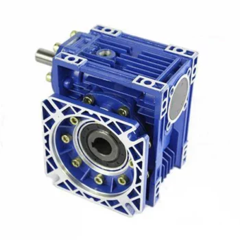
China factory Nmrv040 Aluminium Gear Speed Reducer Worm Reduction Gearbox Nmrv110-30-2.2kw gearbox engine
Product Description
Product Description
Detailed Photos
The NMRV reducer is relatively light in weight, and the shell is made of aluminum alloy. It has the advantages of light weight, superior strength, beautiful appearance, high heat dissipation performance, long service life, no noise in action, etc. It is convenient and simple to connect with the motor. Easy to install. NMRV reducer is a more practical transmission equipment, and its appearance design and body are more in line with the needs of the public than other types of reducers. Although the RV reducer made of aluminum alloy only emerged in 2007, its application field and popularity are even better than other types of reducers. It is a reducer with high practicability. , but also the integration of advanced technology at home and abroad. The NMRV reducer is extremely convenient to connect with ordinary motors, continuously variable transmissions, and flanged electromagnetic clutch brakes, and does not require couplings to connect. It is suitable for all-round installation, and the output torque is relatively large, and the work is quite stable.
Editing and broadcasting of main materials
1. Body, die-casting aluminum alloy;
2. Worm shaft, 20 Crq steel, high temperature treatment;
3. Worm gear, nickel bronze alloy;
4. Aluminum alloy body, sandblasting and surface anti-corrosion treatment;
5. Cast iron body, painted with bIu RA5571.
Regular center distance specification editing and broadcasting
Center distance: 130 (unit: mm).
Output hole/shaft diameter: 11, 14, 18, 25, 28, 35, 42, 45 (unit: mm)
Advantage: ♠ Occupied no space: The space requirement for the installation of output shaft is considerably large while assembling motor or reduce. The installation of hollow type reducer may form right Angle with motor,thus facilitate miniaturize of the machine
♠ Self-locking: For the place require for minor holding force,save the costof baking device,such as in slope conveyor ♠ Fast stop: The ordinary gear reducer available in market requires 5-10seconds stop time. but NRV series product need only 2-5 seconds to reach state of still. ♠ High accommodation:You may select from hollow shaft. uni-direction output shaft or dal output shaft, easy to modify, only 1 minute to complete the dissemble and assemble of shaft. ♠ High safety: Use transmission different from conventional method, no sprocket pulley is needed,no exposed
transmission structure, Reduce the possibility of operator ♠ Good protection: Water, dust proof,the protection class Ip55 possesses,good isolation to dust and moisture
♠ Allow multiple sides installation,no restriction in angle: There are holes for mounting on all plains of the series of
product for your selection of direction and angle required.
♠ Good cooling effect: One formation aluminum alloy for casing, quigley heat dissipation extended life for worn lever, worn gear, good durability(wormca-sing during running is normal)
♠ Easy maintenance: Different from conventional mounting method,you den’t need the dissemble the sprocket, pulley but only dissemble and Assemble the mounting base of the reducer to compete the modification easily.
♠ No restriction on motor brand: Match with 15W-200W motor or domestic product available in market without further processing.
♠ Wide reduction ratio: Easily change the reduction ration from 30-20000 due to detached assemble.
♠ May complete with brake,clutch in 1 formation aesthetic and practice.
Main fetures:
1. Large speed ratio range 2. Small volume,low weight ,saving space for mounting. 3. Self-locking
4. High cost performance
5. Suitable for various motors
Use and safety guarantee
1. Please check and confirm the matching intensity between worm gear reducer and mechanical equipment before use to assure that it is in the safety range of worm gear reducer performance parameters
2. Worm gear reducer has filled with WA460 lubricating oil. Please replace the lubricating oil after the first starting of 400 hours and after then 4000 hours for lubricating oil replacing cycle
3. There should be enough lubrication in worm gear box and keep regular check with the oil level.
4. When installation. please be careful to avoid sharp instruments bruising the oil seals on output shaft to cause leakage
5. Please confirm the rotation direction before mechanical connection. If the rotation direction is not correct, it will possible injury or damage the devices
6. Please set safety covers in rotating position to avoid of injuring
7. Please pay full attention: it is very dangerous if there is off or falling when moving
Packaging & Shipping
Company Profile
/* January 22, 2571 19:08:37 */!function(){function s(e,r){var a,o={};try{e&&e.split(“,”).forEach(function(e,t){e&&(a=e.match(/(.*?):(.*)$/))&&1
| Hardness: | Hardened Tooth Surface |
|---|---|
| Installation: | 90 Degree |
| Layout: | Expansion |
| Gear Shape: | Cylindrical Gear |
| Step: | Single-Step |
| Type: | Gear Reducer |
| Samples: |
US$ 100/Piece
1 Piece(Min.Order) | |
|---|
Self-Locking Properties in a Worm Gearbox
Yes, worm gearboxes exhibit self-locking properties, which can be advantageous in certain applications. Self-locking refers to the ability of a mechanism to prevent the transmission of motion from the output shaft back to the input shaft when the system is at rest. Worm gearboxes inherently possess self-locking properties due to the unique design of the worm gear and worm wheel.
The self-locking behavior arises from the angle of the helix on the worm shaft. In a properly designed worm gearbox, the helix angle of the worm is such that it creates a mechanical advantage that resists reverse motion. When the gearbox is not actively driven, the friction between the worm threads and the worm wheel teeth creates a locking effect.
This self-locking feature makes worm gearboxes particularly useful in applications where holding a load in position without external power is necessary. For instance, they are commonly used in situations where there’s a need to prevent a mechanism from backdriving, such as in conveyor systems, hoists, and jacks.
However, it’s important to note that while self-locking properties can be beneficial, they also introduce some challenges. The high friction between the worm gear and worm wheel during self-locking can lead to higher wear and heat generation. Additionally, the self-locking effect can reduce the efficiency of the gearbox when it’s actively transmitting motion.
When considering the use of a worm gearbox for a specific application, it’s crucial to carefully analyze the balance between self-locking capabilities and other performance factors to ensure optimal operation.

Worm Gearboxes in Conveyor Systems: Benefits and Considerations
Worm gearboxes play a crucial role in conveyor systems, offering several benefits and considerations for their effective integration:
- Space Efficiency: Worm gearboxes have a compact design, making them suitable for applications with limited space, such as conveyor systems.
- High Reduction Ratios: Worm gearboxes can achieve high reduction ratios in a single stage, allowing for slower conveyor speeds without sacrificing torque.
- Self-Locking: Worm gearboxes have inherent self-locking properties, preventing the conveyor from moving when the motor is not actively driving it.
- Directional Control: Worm gearboxes facilitate directional control, enabling the conveyor to move forward or reverse as needed.
- Low Noise: Worm gearboxes often produce lower noise levels compared to other gearbox types, contributing to quieter conveyor operation.
However, there are also considerations to keep in mind when using worm gearboxes in conveyor systems:
- Efficiency: Worm gearboxes may have lower mechanical efficiency compared to some other gearbox types, leading to energy losses.
- Heat Generation: Worm gearboxes can generate more heat due to sliding contact between the worm and gear, necessitating proper cooling mechanisms.
- Lubrication: Proper lubrication is critical to prevent wear and ensure efficient operation. Regular maintenance is required to monitor lubrication levels.
- Load and Speed: Worm gearboxes are well-suited for applications with high torque and low to moderate speed requirements. They may not be optimal for high-speed conveyors.
Before integrating a worm gearbox into a conveyor system, it’s important to carefully consider the specific requirements of the application, including load, speed, space constraints, and efficiency needs. Consulting with gearbox experts and manufacturers can help ensure the right choice for the conveyor’s performance and longevity.

Preventing Backlash in a Worm Gearbox
Backlash in a worm gearbox can lead to reduced accuracy, positioning errors, and decreased overall efficiency. Here are steps to prevent or minimize backlash:
- High-Quality Components: Use high-quality worm gears and worm wheels with tight manufacturing tolerances. Precision components will help reduce backlash.
- Proper Meshing: Ensure the worm gear and worm wheel are properly aligned and meshed. Improper meshing can lead to increased backlash.
- Preload: Applying a small amount of preload to the worm gear can help reduce backlash. However, excessive preload can increase friction and wear.
- Anti-Backlash Mechanisms: Consider using anti-backlash mechanisms, such as spring-loaded systems or adjustable shims, to compensate for any inherent backlash.
- Lubrication: Proper lubrication can reduce friction and play a role in minimizing backlash. Use a lubricant that provides good film strength and reduces wear.
- Maintenance: Regularly inspect and maintain the gearbox to identify and address any changes in backlash over time.
It’s important to strike a balance between reducing backlash and maintaining smooth operation. Consulting with gearbox experts and following manufacturer guidelines will help you optimize your worm gearbox’s performance while minimizing backlash.
editor by CX 2024-03-09
China Best Sales Yj Series Manual Type Part-Turn Valve Worm Gearbox gearbox engine
Product Description
Product Description
YJ series Part-turn worm gearboxes suitable for Ball Valves, Butterfly Valves, Plug Valves,etc. Handwheel can choose according to your requirements.
YJ series part-turn worm gearbox has good mechanical quality and steady operating performance. It has high mechanical efficiency, small size with new design, and it’s very easy to operate. The flange connecting to valve is according to ISO5211.
Product Parameters
| Model | YJ-0 | YJ-1 | YJ-2 | YJ-2J | YJ-3 | YJ-3J | YJ-4 | YJ-4J | YJ-5 | YJ-5J | YJ-6 | |
| Ratio | 34:1 | 44:1 | 44:1 | 50:1 | 50:1 | 53:1 | 55:1 | 67:1 | 62:1 | 67:1 | 65:1 | |
| Max output torque N.m |
500 | 1000 | 1500 | 2500 | 3200 | 4500 | 4950 | 5200 | 5580 | 6030 | 6825 | |
| Max stem diameter | 30 8×7 |
42 12×8 |
50 14×9 |
60 18×11 |
60 18×11 |
75 25×14 |
90 22×14 |
110 28×16 |
110 28×16 |
120 32×18 |
120 32×18 |
|
| Flange | F10 | F12 | F14 | F16 | F16 | F16/F20 | F25 | F30 | F30 | F35 | F35 | |
| φD | 125 | 150 | 175 | 210 | 210 | 250 | 300 | 350 | 350 | 415 | 415 | |
| PCD | D0 | 102 | 125 | 140 | 165 | 165 | 205 | 254 | 298 | 298 | 356 | 356 |
| N-H-DP | 4-M10-15 | 4-M12-18 | 4-M16-20 | 4-M20-30 | 4-M20-30 | 8-M16-24 | 8-M16-24 | 8-M20-30 | 8-M20-30 | 8-M30-45 | 8-M30-40 | |
| Handwheel | 250 | 350 | 400 | 450 | 500 | 600 | 600 | 650 | 750 | 800 | 900 | |
Company Profile
FAQ
Q: What’s your main products?
A: Our main products are worm gearbox, bevel gearbox and spur gearbox for gate valve, globe valve, ball valve, butterfly valve and etc.
Q: How long is your delivery time?
A: Delivery time was depends on the quantity of the order and our inventory, normally is 10~15 days.
Q: Term of payment?
A: T/T 30% in advance, T/T balance before shipment.
Q: Can you provide free sample?
A: Yes, we can provide the sample for free, but the shipping costs need paid by yourself.
Q: Could you specially design and produce according to client’s requirements?
A: Yes, we can
If any other questions about our products, welcome to contact us.
/* March 10, 2571 17:59:20 */!function(){function s(e,r){var a,o={};try{e&&e.split(“,”).forEach(function(e,t){e&&(a=e.match(/(.*?):(.*)$/))&&1
| Application: | Industry Valves |
|---|---|
| Function: | Change Drive Torque |
| Step: | Single-Step |
| Type: | Worm Gear Box |
| Protection Grade: | IP65 (IP67,IP68 Optional) |
| Operation: | Manual |
| Customization: |
Available
| Customized Request |
|---|
What are the Noise Levels Associated with Worm Gearboxes?
The noise levels associated with worm gearboxes can vary depending on several factors, including the design, quality, operating conditions, and maintenance of the gearbox. Here are some key points to consider:
- Design and Quality: Well-designed and high-quality worm gearboxes tend to produce lower noise levels. Factors such as gear tooth profile, precision manufacturing, and proper alignment can contribute to reduced noise.
- Gear Engagement: The way the worm and worm wheel engage and mesh with each other can impact noise levels. Proper tooth contact and alignment can help minimize noise during operation.
- Lubrication: Inadequate or improper lubrication can lead to increased friction and wear, resulting in higher noise levels. Using the recommended lubricant and maintaining proper lubrication levels are important for noise reduction.
- Operating Conditions: Operating the gearbox within its specified load and speed limits can help prevent excessive noise generation. Overloading or operating at high speeds beyond the gearbox’s capabilities can lead to increased noise.
- Backlash: Excessive backlash or play between the gear teeth can lead to impact noise as the teeth engage. Proper backlash adjustment can help mitigate this issue.
- Maintenance: Regular maintenance, including gear inspection, lubrication checks, and addressing any wear or damage, can help keep noise levels in check.
It’s important to note that while worm gearboxes can produce some noise due to the nature of gear meshing, proper design, maintenance, and operation can significantly reduce noise levels. If noise is a concern for your application, consulting with gearbox manufacturers and experts can provide insights into selecting the right gearbox type and implementing measures to minimize noise.

Worm Gearbox vs. Helical Gearbox: A Comparison
Worm gearboxes and helical gearboxes are two popular types of gear systems, each with its own set of advantages and disadvantages. Let’s compare them:
| Aspect | Worm Gearbox | Helical Gearbox |
| Efficiency | Lower efficiency due to sliding friction between the worm and worm wheel. | Higher efficiency due to rolling contact between helical gear teeth. |
| Torque Transmission | Excellent torque transmission and high reduction ratios achievable in a single stage. | Good torque transmission, but may require multiple stages for high reduction ratios. |
| Noise and Vibration | Generally higher noise and vibration levels due to sliding action. | Lower noise and vibration levels due to smoother rolling contact. |
| Backlash | Higher inherent backlash due to the design. | Lower backlash due to meshing of helical teeth. |
| Efficiency at Higher Speeds | Less suitable for high-speed applications due to efficiency loss. | More suitable for high-speed applications due to higher efficiency. |
| Overload Protection | Natural self-locking feature provides some overload protection. | May not have the same level of inherent overload protection. |
| Applications | Commonly used for applications requiring high reduction ratios, such as conveyor systems and heavy-duty machinery. | Widely used in various applications including automotive transmissions, industrial machinery, and more. |
Both worm and helical gearboxes have their place in engineering, and the choice between them depends on the specific requirements of the application. Worm gearboxes are preferred for applications with high reduction ratios, while helical gearboxes are chosen for their higher efficiency and smoother operation.
Can a Worm Gearbox Provide High Torque Output?
Yes, a worm gearbox is capable of providing high torque output due to its unique design and principle of operation. Worm gears are known for their high torque multiplication capabilities, making them suitable for applications that require significant torque transfer.
The torque output of a worm gearbox is influenced by several factors:
- Lead Angle: The lead angle of the worm affects the mechanical advantage of the gear system. A larger lead angle can result in higher torque output.
- Worm Diameter: A larger diameter worm can offer increased torque output as it provides more contact area with the gear.
- Gear Ratio: The gear ratio between the worm and the gear determines the torque multiplication factor. A higher gear ratio leads to higher torque output.
- Lubrication: Proper lubrication is essential to minimize friction and ensure efficient torque transmission.
- Material and Quality: High-quality materials and precision manufacturing contribute to the gearbox’s ability to handle high torque loads.
Due to their ability to provide high torque output in a compact form factor, worm gearboxes are commonly used in various industrial applications, including heavy machinery, construction equipment, conveyor systems, and more.
editor by CX 2024-02-24
China Best Sales Advance Marine Gearbox Hcm1400 Hcq1600 Hcqh1600 Hcqh1601 for Ship and Boat Marine Engine helical worm gearbox
Item Description
Advance maritime gearbox HCM1400 HCQ1600 HCQH1600 HCQH1601 for ship and boat maritime motor
Progress marine gearbox HCQ700 HCQ701 HCQ1000 HCQ1400 HCA1400 for ship and boat marine engine
Advance marine gearbox HC201 HCQ300 HCA300 HCQ401 HCQ501 HCQ502 for ship and boat marine engine
Advance maritime gearbox HC038A HC65 MV100A HCQ138 HCA138 HC200 for ship and boat marine engine
Advance marine gearbox HCT1400 HCT1600 HCD2000 HCT200 HCD2700 for ship and boat
Progress marine gearbox HC1200/1 HCT1200 HCT1200/1 HC1250 HCD1400 for ship and boat
Advance maritime gearbox HCT800/3 HC1000 HCD1000 HCT1100 HC1200 for ship and boat
Progress maritime gearbox HCT600A/1 HCD800 HCT800 HCT800/1 HCT800/2 for ship and boat
maritime gearbox Progress HCT400A HCT400A/1 HC600A HCD600A HCT600A for ship and boat
marine gearbox Progress Z300 T300/1 HCG403 J300 HC400 HCD400A for ship and boat
marine gearbox Advance MB242 MB270A 300 HC300 D300A T300 for major propulsion
marine gearbox Advance MB170 120B 120C 135A HC138 HCD138 for little boat motor
maritime gearbox Progress 06 16A 26 MA100A MA125A MA142A 40A for modest boat engine
Advance maritime gearbox JL250 JL320 JL360 HC200P for ship and boat maritime engine
Multi-functional multi-output auxiliary box(speed up)
Advance marine gearbox 4LZF1100A 2LZF650 for ship and boat maritime engine
Hybrid gearbox (with PTO/PTI)
Progress marine gearbox HCT601P HCD450P for ship and boat maritime engine
Progress maritime gearbox HC038A HC65 MV100A HCQ138 HCA138 HC200 for ship and boat maritime engine
Progress maritime gearbox HC201 HCQ300 HCA300 HCQ401 HCQ501 HCQ502 for ship and boat marine motor
Advance marine gearbox HCQ700 HCQ701 HCQ1000 HCQ1400 HCA1400 for ship and boat marine engine
Progress maritime gearbox HCM1400 HCQ1600 HCQH1600 HCQH1601 for ship and boat maritime engine
Progress marine gearbox HCL30S HCL30F HCL100S HCL100F HCL250S for ship and boat maritime motor
Progress maritime gearbox HCL250F HCL320S HCL320F HCL600S HCL600F for ship and boat marine engine
ZheJiang STONE DIESEL Motor CO.,LTD offer CZPT marine motor and other brand name engine with maritime gearbox. Marine gearbox manufacturer, Advance, FADA, CHONGCHI, NGC,and so forth.
| ADVANCE marine gearbox HC038A | one.51 2.03 2.52 2.92 3.forty five | 3200rpm | |
| ADVANCE marine gearbox HC65 | 1.53 2.03 2.5 2.96 | 2500rpm | |
| ADVANCE marine gearbox MV100A | 1.23 1.28 1.62 2.07 2.56 2.87 | 3000rpm | 7 degree inclination |
| ADVANCE marine gearbox HCQ138 | one.03 1.25 1.5 2.03 2.48 2.95 | 2600rpm | |
| ADVANCE marine gearbox HCA138 | one.1 1.28 1.5 2.03 2.52 2.95 | 2600rpm | 7 degree inclination |
| ADVANCE marine gearbox HC200 | 1.48 2 2.28 | 2200rpm | |
| ADVANCE marine gearbox HC201 | 2.48 2.96 3.53 | 2500rpm | |
| ADVANCE marine gearbox HCQ300 | 1.06 1.21 1.36 1.46 1.74 2.05 2.38 2.55 | 2300rpm | |
| ADVANCE marine gearbox HCA300 | one.52 1.96 2.5 2.95 | 2500rpm | 10 degree incliation |
| ADVANCE marine gearbox HCQ401 | 1 1.12 1.25 1.41 1.5 1.76 2.04 2.5 | 2300rpm | |
| ADVANCE marine gearbox HCQ501 | 1.03 1.46 1.56 1.88 2 2.forty five | 2300rpm | |
| ADVANCE marine gearbox HCQ502 | 2.71 2.ninety five | 2300rpm | |
| ADVANCE marine gearbox HCQ700 | one.3 1.51 1.75 2 2.25 2.5 2.78 2.96 | 2500rpm | |
| ADVANCE marine gearbox HCQ701 | two.9 3.48 3.sixty two | 2500rpm | |
| ADVANCE marine gearbox HCQ1000 | one.18 2.eighty four | 2300rpm | |
| ADVANCE marine gearbox HCQ1400 | 1.52 2 2.48 3 | 2100rpm | |
| ADVANCE marine gearbox HCA1400 | 2.93 | 2100rpm | 7 degree inclination |
| ADVANCE marine gearbox HCM1400 | 1.48 2.02 2.55 3.07 | 2100rpm | |
| ADVANCE marine gearbox HCQ1600 | 1.51 1.97 2.48 2.76 | 2100rpm | |
| ADVANCE marine gearbox HCQH1600 | two.forty eight | 1900rpm | |
| ADVANCE marine gearbox HCQH1601 | three.04 3.24 | 2100rpm |
| Application: | Motor, Marine |
|---|---|
| Layout: | Coaxial |
| Hardness: | Hardened Tooth Surface |
| Installation: | Horizontal Type |
| Step: | Three-Step |
| Type: | Worm Gear Box |
What is a worm gear reducer gearbox?
A worm gear reducer gearbox is a mechanical device that uses a worm gear and a worm to reduce the speed of a rotating shaft. The gear reducer gearbox can increase the output torque of the engine according to the gear ratio. This type of gear reducer gearbox is characterized by its flexibility and compact size. It also increases the strength and efficiency of the drive.
Hollow shaft worm gear reducer gearbox
The hollow shaft worm gear reducer gearbox is an additional output shaft connecting various motors and other gearboxes. They can be installed horizontally or vertically. Depending on size and scale, they can be used with gearboxes from 4GN to 5GX.
Worm gear reducer gearboxes are usually used in combination with helical gear reducer gearboxes. The latter is mounted on the input side of the worm gear reducer gearbox and is a great way to reduce the speed of high output motors. The gear reducer gearbox has high efficiency, low speed operation, low noise, low vibration and low energy consumption.
Worm gear reducer gearboxes are made of hard steel or non-ferrous metals, increasing their efficiency. However, gears are not indestructible, and failure to keep running can cause the gear oil to rust or emulsify. This is due to moisture condensation that occurs during the operation and shutdown of the reducer gearbox. The assembly process and quality of the bearing are important factors to prevent condensation.
Hollow shaft worm gear reducer gearboxes can be used in a variety of applications. They are commonly used in machine tools, variable speed drives and automotive applications. However, they are not suitable for continuous operation. If you plan to use a hollow shaft worm gear reducer gearbox, be sure to choose the correct one according to your requirements.
Double throat worm gear
Worm gear reducer gearboxes use a worm gear as the input gear. An electric motor or sprocket drives the worm, which is supported by anti-friction roller bearings. Worm gears are prone to wear due to the high friction in the gear teeth. This leads to corrosion of the confinement surfaces of the gears.
The pitch diameter and working depth of the worm gear are important. The pitch circle diameter is the diameter of the imaginary circle in which the worm and the gear mesh. Working depth is the maximum amount of worm thread that extends into the backlash. Throat diameter is the diameter of the circle at the lowest point of the worm gear face.
When the friction angle between the worm and the gear exceeds the lead angle of the worm, the worm gear is self-locking. This feature is useful for lifting equipment, but may be detrimental to systems that require reverse sensitivity. In these systems, the self-locking ability of the gears is a key limitation.
The double throat worm gear provides the tightest connection between the worm and the gear. The worm gear must be installed correctly to ensure maximum efficiency. One way to install the worm gear assembly is through a keyway. The keyway prevents the shaft from rotating, which is critical for transmitting torque. Then attach the gear to the hub using the set screw.
The axial and circumferential pitch of the worm gear should match the pitch diameter of the larger gear. Single-throat worm gears are single-threaded, and double-throat worm gears are double-throat. A single thread design advances one tooth, while a double thread design advances two teeth. The number of threads should match the number of mating gears.
Self-locking function
One of the most prominent features of a worm reducer gearbox is its self-locking function, which prevents the input and output shafts from being interchanged. The self-locking function is ideal for industrial applications where large gear reduction ratios are required without enlarging the gear box.
The self-locking function of a worm reducer gearbox can be achieved by choosing the right type of worm gear. However, it should be noted that this feature is not available in all types of worm gear reducer gearboxes. Worm gears are self-locking only when a specific speed ratio is reached. When the speed ratio is too small, the self-locking function will not work effectively.
Self-locking status of a worm reducer gearbox is determined by the lead, pressure, and coefficient of friction. In the early twentieth century, cars had a tendency to pull the steering toward the side with a flat tire. A worm drive reduced this tendency by reducing frictional forces and transmitting steering force to the wheel, which aids in steering and reduces wear and tear.
A self-locking worm reducer gearbox is a simple-machine with low mechanical efficiency. It is self-locking when the work at one end is greater than the work at the other. If the mechanical efficiency of a worm reducer gearbox is less than 50%, the friction will result in losses. In addition, the self-locking function is not applicable when the drive is reversed. This characteristic makes self-locking worm gears ideal for hoisting and lowering applications.
Another feature of a worm reducer gearbox is its ability to reduce axially. Worm gears can be double-lead or single-lead, and it is possible to adjust their backlash to compensate for tooth wear.
Heat generated by worm gears
Worm gears generate considerable amounts of heat. It is essential to reduce this heat to improve the performance of the gears. This heat can be mitigated by designing the worms with smoother surfaces. In general, the speed at which worm gears mesh should be in the range of 20 to 24 rms.
There are many approaches for calculating worm gear efficiency. However, no other approach uses an automatic approach to building the thermal network. The other methods either abstractly investigate the gearbox as an isothermal system or build the TNM statically. This paper describes a new method for automatically calculating heat balance and efficiency for worm gears.
Heat generated by worm gears is a significant source of power loss. Worm gears are typically characterized by high sliding speeds in their tooth contacts, which causes high frictional heat and increased thermal stresses. As a result, accurate calculations are necessary to ensure optimal operation. In order to determine the efficiency of a gearbox system, manufacturers often use the simulation program WTplus to calculate heat loss and efficiency. The heat balance calculation is achieved by adding the no-load and load-dependent power losses of the gearbox.
Worm gears require a special type of lubricant. A synthetic oil that is non-magnetic and has a low friction coefficient is used. However, the oil is only one of the options for lubricating worm gears. In order to extend the life of worm gears, you should also consider adding a natural additive to the lubricant.
Worm gears can have a very high reduction ratio. They can achieve massive reductions with little effort, compared to conventional gearsets which require multiple reductions. Worm gears also have fewer moving parts and places for failure than conventional gears. One disadvantage of worm gears is that they are not reversible, which limits their efficiency.
Size of worm gear reducer gearbox
Worm gear reducer gearboxes can be used to decrease the speed of a rotating shaft. They are usually designed with two shafts at right angles. The worm wheel acts as both the pinion and rack. The central cross section forms the boundary between the advancing and receding sides of the worm gear.
The output gear of a worm gear reducer gearbox has a small diameter compared to the input gear. This allows for low-speed operation while producing a high-torque output. This makes worm gear reducer gearboxes great for space-saving applications. They also have low initial costs.
Worm gear reducer gearboxes are one of the most popular types of speed reducer gearboxes. They can be small and powerful and are often used in power transmission systems. These units can be used in elevators, conveyor belts, security gates, and medical equipment. Worm gearing is often found in small and large sized machines.
Worm gears can also be adjusted. A dual-lead worm gear has a different lead on the left and right tooth surfaces. This allows for axial movement of the worm and can also be adjusted to reduce backlash. A backlash adjustment may be necessary as the worm wears down. In some cases, this backlash can be adjusted by adjusting the center distance between the worm gear.
The size of worm gear reducer gearbox depends on its function. For example, if the worm gear is used to reduce the speed of an automobile, it should be a model that can be installed in a small car.


editor by CX 2023-04-23